Eurobot
RCVA (Robot Concept Ville d’Avray) is a team of students who designs, manufactures and programs two autonomous robots each year for the Eurobot international competition. I was part of the team in 2018-19 (Leader) and 2019-20.
Video
Video presentation related to the RCVA project:
Gallery
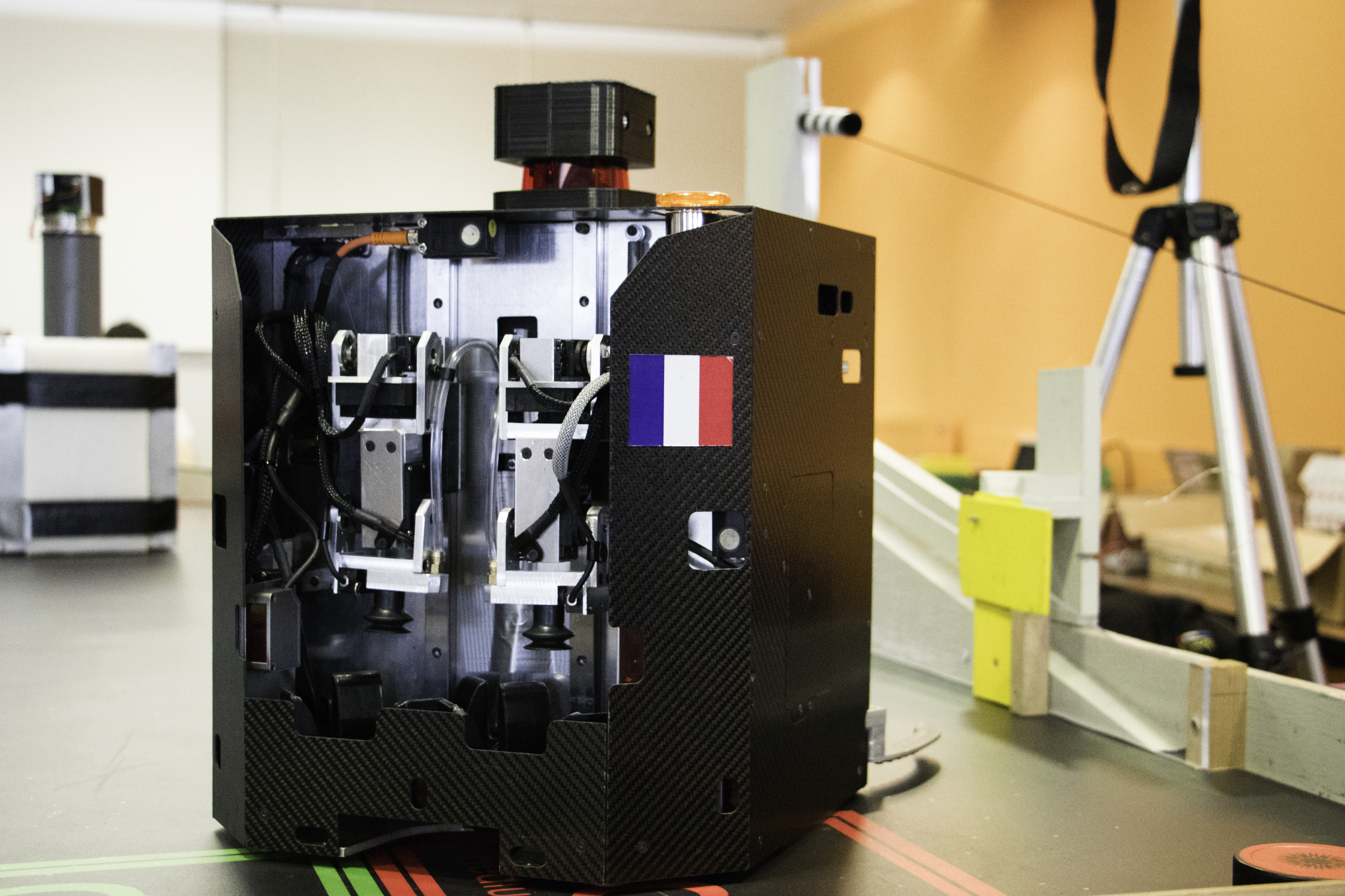
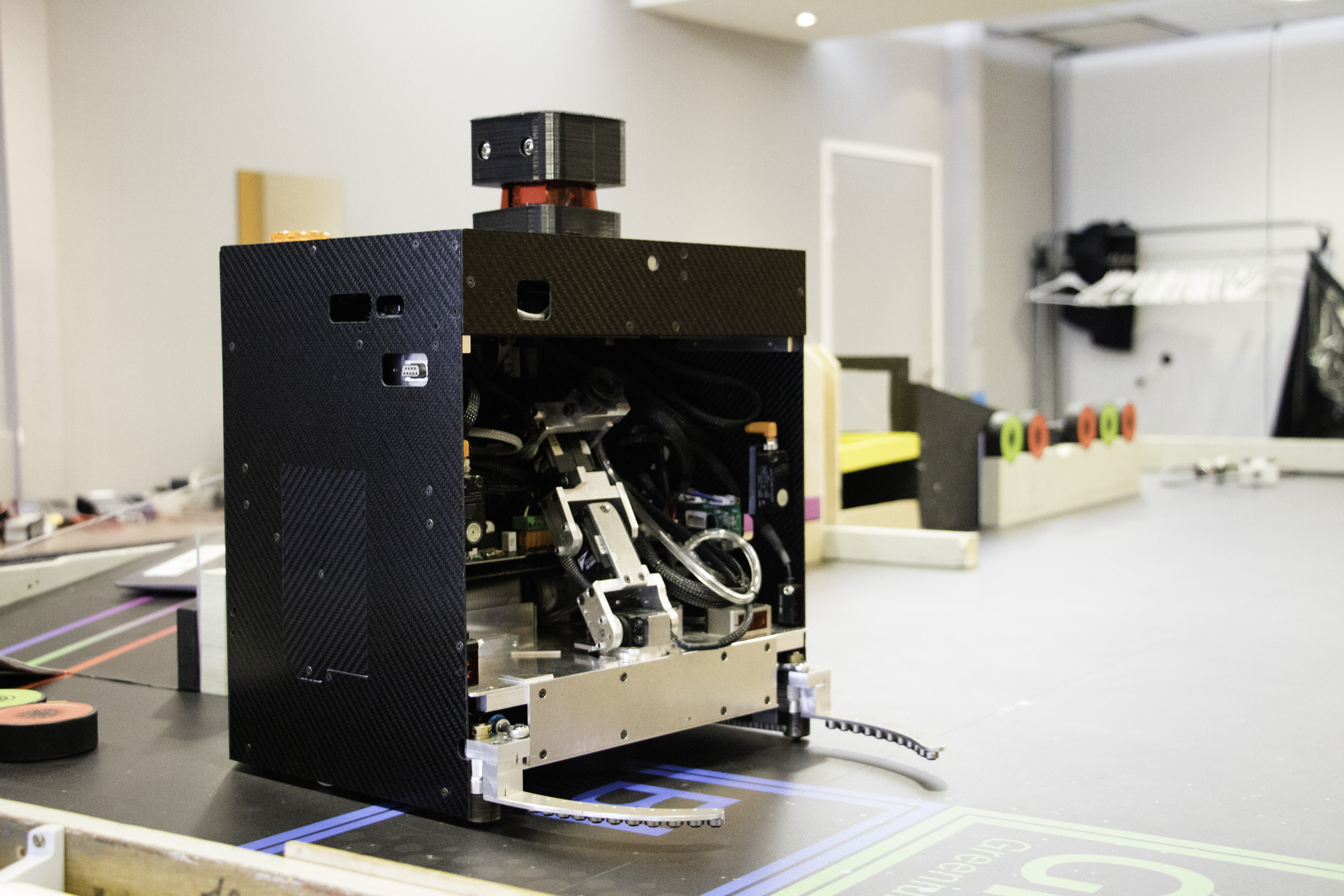
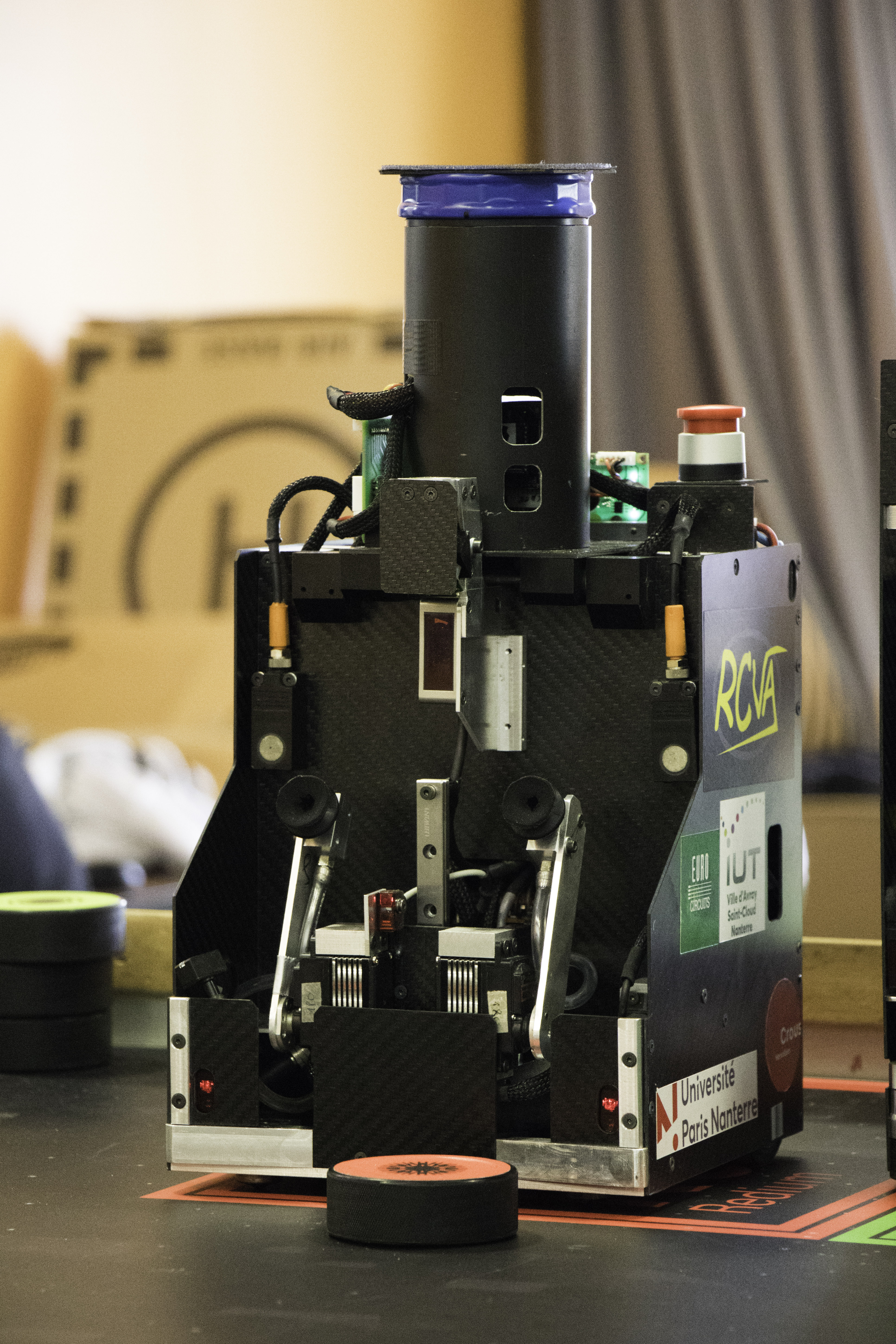
Personal contributions
- Full routing of the small and big robots’ motherboards (Eagle).
- Created a bootloader for Cypress PSoC5LP to program the microcontrollers over an XBee link.
- Complete development of the small robot’s SLAM.
- Mechanical design, soldering and integration; ESC test bench; Lidar integration and debugging.
RCVA mid‑project report
I. Routing with Eagle
A. Schematic & footprints
Schematic done in Eagle with the RCVA library. The Cypress PSoC5LP footprint was created specifically this year. Notable PSoC points:
- Pins 12_* cannot be used as analog inputs, but they are the only ones that support a logic level different from 5 V. They can source up to 25 mA.
- All grounds (GND) and all VCCs are properly interconnected (planes and stitching vias).
- 24 MHz crystal with 18 pF capacitors.
- Level shifting for sensors via resistor dividers from 15 V → 5 V.
B. Routing
Since PSoC pins are assignable, I organized functional buses (sensors, actuators, comms) and routed by blocks to improve readability and maintainability. Also made the small robot’s motherboard (with Pierre).
Good practices kept:
- Multiply ground test points and take care of return currents.
- Avoid routing traces between PSoC pins.
- Route as much as possible on one layer before using the second to limit vias.
II. XBee (API mode)
Developed an XBee library in API mode: explicit addressing of the recipient and acknowledgments. Example of a broadcast frame sending “bonjour”:
Start  Len1 Len2  ID  Type  Adr64 ...            Adr16  Opt  Opt  Payload("bonjour")  Checksum
0x7E   0x00  0x15  0x01 0x10  0x00 0x00 0x00 0x00 0xFF 0xFF  0x00  0x00  0x00  0x00  0x62 0x6F 0x6E 0x6A 0x6F 0x75 0x72  0xF2
Next step: integration with the cracboomhue system via XBee.
III. Mechanics
Followed the mechanical design of the robots and the integration with electronics (interfaces, mounts, maintenance access).
IV. Experiment (ESC bench)
Arduino test bench for “emax mini” ESC: initialization at 1000 µs then ramp to 1500 µs (+10 every 50 ms), with a front‑panel switch to cut the turbine. I’ll add the code after a rewrite.
V. Lidar
Continuous UART read with DMA. Initial desynchronization PSoC ⇄ Lidar solved on 12/28 via hysteresis state detection (instead of sampling). Successful tests (despite imperfections) and decision to use the Lidar on the big robot.
VI. Small robot SLAM
Full development: Lidar + odometry acquisition, occupancy‑grid mapping, periodic re‑alignment (scan matching), and pose estimation robust to light collisions. Tuning adapted to the small robot’s size and speeds.
Objectives
- Design, build and program a main robot (and possibly a secondary one) compliant with the current rules.
- Reach robustness, precision and repeatability to score points autonomously and safely.
- Learn by doing in mechanics, electronics, embedded software and planning.
- Document and keep the know‑how for future editions.
Technical scope
Mechanical
- Chassis optimized for stiffness/weight, modular integration, fast maintenance.
- Actuators (grippers, lifts, conveyors) tailored to the rulebook tasks.
Electronics
- Custom PCBs: power, motor drivers, sensor I/O, protections.
- Sensors: odometry, IMU, ranging (budget permitting) with safety redundancy (E‑stop).
Software
- Real‑time software architecture: control/loops, logging.
- Localization and navigation: odometry + correction, planning, avoidance.
- Match strategies: state machine, dynamic choice based on time/score.