Balyo — R&D Electronics Internship
April — July 2019 · Paris, France
Objective
Redesign the electronics architecture of the Sherpa autonomous robot to make it industrializable, simpler to integrate, and ready for production. The focus was on communication interfaces, safety circuitry, and custom PCB design.
Robot context
Sherpa is a mobile robot used to move cartons in warehouses. Navigation relies on LiDAR‑based SLAM; safety relies on two SICK laser scanners and a pressure‑sensitive bumper. The lower module houses the electronics (sensors, motors, onboard PC, battery) while the upper module contains the HMI and the payload area.
Initial architecture and costs
Before the redesign, the prototype used several off‑the‑shelf boxes in addition to two custom boards. The main items and approximate costs were:
| Component | Qty | Role | Cost |
|---|---|---|---|
| Industrial PC (MOVEBOX) | 1 | Main compute | ≈ 1500€ |
| Balyo AnumES I/O boards | 2 | Analog LED driving | ≈ 300€ |
| MOXA serial↔Ethernet converters | 2 | RS485/422 to Ethernet | ≈ 700€ |
| Ethernet switch | 1 | Network fan‑out | ≈ 100€ |
| Custom boards (IHM, SAFety) | 2 | HMI + Power/Safety | ≈ 300€ |
Total prototype cost: roughly 3000€ per robot.
System architecture
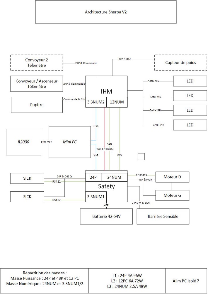
The Sherpa embeds a navigation stack (LiDAR for SLAM), safety sensors, motors and an onboard PC. Electronics were re-architected around two custom boards: an upper HMI board and a lower SAFety board. Keeping two boards allowed the use of off‑the‑shelf sealed enclosures given the connector pin limits available in waterproof housings.
Communication and interfaces
- Replaced external serial‑to‑Ethernet servers with onboard RS485/RS422 transceivers driven by a MCU.
- Introduced a Cypress microcontroller with native USB to interface the PC ↔ boards, removing the Ethernet switch.
- Kept Ethernet where required (e.g., LiDAR to PC) and consolidated remaining I/O on the custom boards.
- HMI board now generates required analog levels for LED control, removing two external I/O boards.
Safety loop redesign
- Implemented a redundant, diagnosable safety loop to meet performance level requirements.
- Replaced bulky relays with power MOSFETs for compactness and reliability.
- High‑side switching of the 48 V bus achieved with N‑channel MOSFETs driven via an isolated DC/DC gate supply referenced to the source, ensuring proper gate overdrive.
Mechanical, connectors and harnessing
- Waterproof enclosures constrained I/O to ≈60 pins per housing, motivating the two‑board split.
- Defined harnesses and cable drawings between boards, motors, safety sensors and HMI elements.
- Separated power and digital grounds; isolated interfaces to motors and encoders using optocouplers.
PCB design
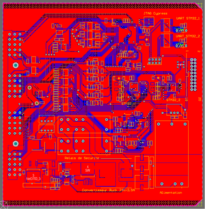
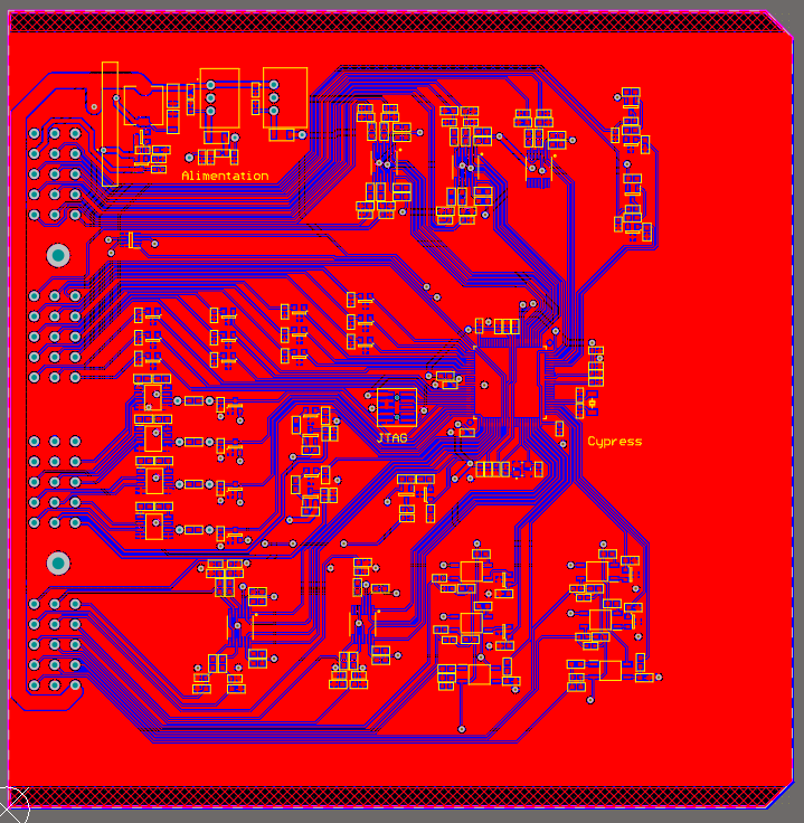
- Designed in Altium (chosen for compatibility with existing sources and lower cost).
- Separated power and digital grounds; interfaced motors and safety sensors via optocouplers.
- Used high‑speed optocouplers for incremental encoder feedback.
Firmware and validation
- Developed low‑level firmware on the Cypress MCU for USB communication and RS485/422 drivers.
- Implemented diagnostics for the safety loop and sensor state reporting to the PC.
- Performed bring‑up, continuity and functional tests on first articles prior to integration.
Results and impact
- Removed two MOXA converters, two external AnumES I/O boards and one Ethernet switch.
- Reduced BOM by approximately 1100€ per robot while simplifying integration and wiring.
- Prepared the design for industrialization with sealed enclosures and clear harness definitions.